Wednesday, 30 December 2015

Biological Computers

Abstract

Biological computers have emerged as an interdisciplinary field that draws together molecular biology, chemistry, computer science and mathematics. The highly predictable hybridization chemistry of DNA, the ability to completely control the length and content of oligonucleotides, and the wealth of enzymes available for modification of the DNA, make the use of nucleic acids an attractive candidate for all of these nanoscale applications.
A 'DNA computer' has been used for the first time to find the only correct answer from over a million possible solutions to a computational problem. Leonard Adleman of the University of Southern California in the US and colleagues used different strands of DNA to represent the 20 variables in their problem, which could be the most complex task ever solved without a conventional computer. The researchers believe that the complexity of the structure of biological molecules could allow DNA computers to outperform their electronic counterparts in future.

Scientists have previously used DNA computers to crack computational problems with up to nine variables, which involves selecting the correct answer from 512 possible solutions. But now Adleman's team has shown that a similar technique can solve a problem with 20 variables, which has 220 - or 1 048 576 - possible solutions.
Adleman and colleagues chose an 'exponential time' problem, in which each extra variable doubles the amount of computation needed. This is known as an NP-complete problem, and is notoriously difficult to solve for a large number of variables. Other NP-complete problems include the 'travelling salesman' problem - in which a salesman has to find the shortest route between a number of cities - and the calculation of interactions between many atoms or molecules.
Adleman and co-workers expressed their problem as a string of 24 'clauses', each of which specified a certain combination of 'true' and 'false' for three of the 20 variables. The team then assigned two short strands of specially encoded DNA to all 20 variables, representing 'true' and 'false' for each one.
In the experiment, each of the 24 clauses is represented by a gel-filled glass cell. The strands of DNA corresponding to the variables - and their 'true' or 'false' state - in each clause were then placed in the cells.
Each of the possible 1,048,576 solutions were then represented by much longer strands of specially encoded DNA, which Adleman's team added to the first cell. If a long strand had a 'subsequence' that complemented all three short strands, it bound to them. But otherwise it passed through the cell.
To move on to the second clause of the formula, a fresh set of long strands was sent into the second cell, which trapped any long strand with a 'subsequence' complementary to all three of its short strands. This process was repeated until a complete set of long strands had been added to all 24 cells, corresponding to the 24 clauses. The long strands captured in the cells were collected at the end of the experiment, and these represented the solution to the problem.

DOCTOR IN A CELL

In previous Biological computers produced input, output and "software" are all composed of DNA, the material of genes, while DNA-manipulating enzymes are used as "hardware." The newest version's input apparatus is designed to assess concentrations of specific RNA molecules, which may be overproduced or under produced, depending on the type of cancer. Using pre-programmed medical knowledge, the computer then makes its diagnosis based on the detected RNA levels.
In response to a cancer diagnosis, the output unit of the computer can initiate the controlled release of a single-stranded DNA molecule that is known to interfere with the cancer cell's activities, causing it to self-destruct.

Rain Technology

Abstract

Rain finity's technology originated in a research project at the California Institute of Technology (Caltech), in collaboration with NASA's Jet Propulsion Laboratory and the Defense Advanced Research Projects Agency (DARPA).The name of the original research project was RAIN, which stands for Reliable Array of Independent Nodes. The goal of the RAIN project was to identify key software building blocks for creating reliable distributed applications using off-the-shelf hardware.
The focus of the research was on high-performance, fault-tolerant and portable clustering technology for space-borne computing. Two important assumptions were made, and these two assumptions reflect the differentiations between RAIN and a number of existing solutions both in the industry and in academia:
1. The most general share-nothing model is assumed. There is no shared storage accessible from all computing nodes. The only way for the computing nodes to share state is to communicate via a network. This differentiates RAIN technology from existing back-end server clustering solutions such as SUNcluster, HP MC Serviceguard or Microsoft Cluster Server.
2. The distributed application is not an isolated system. The distributed protocols interact closely with existing networking protocols so that a RAIN cluster is able to interact with the environment. Specifically, technological modules were created to handle high-volume network-based transactions. This differentiates it from traditional distributed computing projects such as Beowulf.
In short, the RAIN project intended to marry distributed computing with networking protocols. It became obvious that RAIN technology was well-suited for Internet applications. During the RAIN project, key components were built to fulfill this vision. A patent was filed and granted for the RAIN technology. Rainfinity was spun off from Caltech in 1998, and the company has exclusive intellectual property rights to the RAIN technology. After the formation of the company, the RAIN technology has been further augmented, and additional patents have been filed.
The guiding concepts that shaped the architecture are as follows:

1. Network Applications

The architecture goals for clustering data network applications are different from clustering data storage applications. Similar goals apply in the telecom environment that provides the Internet backbone infrastructure, due to the nature of applications and services being clustered.

2. Shared-Nothing

The shared-storage cluster is the most widely used for database and application servers that store persistent data on disks. This type of cluster typically focuses on the availability of the database or application service, rather than performance. Recovery from failover is generally slow, because restoring application access to disk-based data takes minutes or longer, not seconds. Telecom servers deployed at the edge of the network are often diskless, keeping data in memory for performance reasons, and tolerate low failover time. Therefore, a new type of share-nothing cluster with rapid failure detection and recovery is required. The only way for the shared-nothing cluster to share is to communicate via the network.

3. Scalability

While the high-availability cluster focuses on recovery from unplanned and planned downtimes, this new type of cluster must also be able to maximize I/O performance by load balancing across multiple computing nodes. Linear scalability with network throughput is important. In order to maximize the total throughput, load load-balancing decisions must be made dynamically by measuring the current capacity of each computing node in real-time. Static hashing does not guarantee
an even distribution of traffic.

4. Peer-to-Peer

A dispatcher-based, master-slave cluster architecture suffers from scalability by introducing a potential bottleneck. A peer-to-peer cluster architecture is more suitable for latency-sensitive data network applications processing shortlived sessions. A hybrid architecture should be considered to offset the need for more control over resource management. For example, a cluster can assign multiple authoritative computing nodes that process traffic in the round-robin order for each network interface that is clustered to reduce the overhead of traffic forwarding.

Bluetooth Broadcasting

Abstract

Bluetooth wireless technology (IEEE 802.15.1) is a short-range communications technology originally intended to replace the cables connecting portable and/or fixed devices while maintaining high levels of security.The key features of Bluetooth technology are threefold:
  • robustness
  • low power
  • low cost.
 Bluetooth has been designed in a uniform way. This way it enables a wide range of devices to connect and communicate with each other by using the Bluetooth wireless communication protocol. The Bluetooth technology has achieved global acceptance in such a way that any Bluetooth-enabled electronic device, almost everywhere in the world, is able to connect to other Bluetooth-enabled devices in its proximity.
Bluetooth-enabled electronic devices connect and communicate wirelessly through short-range, ad hoc networks known as piconets. Each device can simultaneously communicate with up to seven other devices within a single piconet. Each device can also belong to several piconets simultaneously. Piconets are established dynamically and automatically as Bluetooth-enabled devices enter and leave radio proximity. One of the main strengths of the Bluetooth wireless technology is the ability to handle data and voice transmissions simultaneously. This enables users to use a hands-free headset for voice calls, printing, fax capabilities, synchronizing PDA’s, laptops, and mobile phone applications to name a few.
An important aspect of this thesis is about the scalability of Bluetooth broadcasting. Since scalability can sometimes be a rather vague concept, we give a short explanation of the term. An important aspect of software products is how they are able to cope with growth. For example, how does the system handle an increase in users or data traffic? This property of a software system is usually referred to as scalability. A more detailed specification of the concept is given by AndrĂ© Bondi, who defines it as follows: ‘Scalability is a desirable attribute of a network, system, or process.
The concept connotes the ability of a system to accommodate an increasing number of elements or objects, to process growing volumes of work gracefully, and/or to be susceptible to enlargement.’ Whenever a system meets these requirements we can say that the system scales. In this thesis scalability comes down to the question if the system is capable of dealing with large groups of users equipped with Bluetooth enabled devices capable of receiving simple text messages.

Passive Broadcasting

The first type of business deals with broadcasting from a central location, which we will call passive broadcasting. Most of these companies sell both the hardware and software to enable this. For example, BlueCasting by Filter WorldWide, one of the major players in the market which made the news in August 2005 when they distributed merchandise for the British pop band Coldplay, offers a product family divided into four types of systems. They offer solutions for small retail shops, one-off events such as music festivals, and even larger areas such as airports and train stations.
The latest descendant in the family is a system that provides an interactive touchscreen allowing users to interact directly with the system. BlueCasting is an example of a product that comes with both hardware (one or more BlueCast Servers) and software (BlueCast Campaign Management System) which is used to provide remote setup, maintenance and reporting.Besides this type of companies, i.e. the ones that are selling the total package, other companies have dedicated themselves to providing just the hardware. An example is BlueGiga. According to their website their BlueGiga Access Servers are used by more than 350 Bluetooth Marketing companies in more than 65 countries. They sell two lines of products: Bluetooth Modules and Bluetooth Access Servers. The modules are described as ‘completely integrated, certified, high-performance Radio Frequency products including all needed Bluetooth profiles’.
Access Servers are sold in the form of Access Points (up to 7 connections) and Access Servers (up to 21 connections). Besides this they also sell the BlueGiga Solution Manager (BSM). This is a web-based remote management and monitoring platform for BlueGiga Access Servers that can be used to simultaneously upgrade, monitor and configure a large number of BlueGiga Access Servers, instead of configuring each device one-by-one.

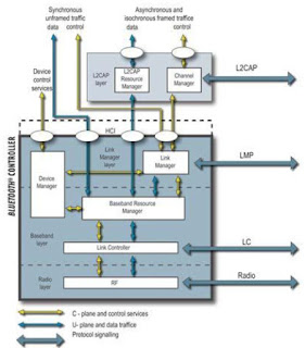
Bluetooth Core System Architecture :

The transceiver operates in the globally unlicensed ISM band at 2.4 GHz. The bit rate
is 1 Megabit per second and can be boosted to 2 or 3 Mb/s with Enhanced Data Rate[EDR]. The 79 channels in the band are ordered from channel number 0-78 and are spaced 1 MHz beginning at 2402 GHz. Bluetooth-enabled devices that are communicating share a radio channel and are synchronized to a common clock and frequency hopping pattern. Frequency hopping is used to make the protocol more-robust to interference from other devices operating in the same band.
The physical channel is sub-divided into time units known as slots. Data is transmitted between Bluetooth-enabled devices in packets. These packets are situated in the slots. Packets can fill one or more consecutive slots, allowing larger data chunks to be transmitted if the circumstances admit this. Bluetooth is primarily designed for low power consumption and affordability and has a relatively short range (1, 10 or 100 meters). It makes use of low-cost transceiver microchips that are embedded in each device.
The Bluetooth Base band is the part of the Bluetooth system that specifies or implements the medium access and physical layer procedures between Bluetooth devices. Several devices can be joined together in what is called a piconet. One device owns the clock and the frequency hopping pattern and is called the master. Two or more piconets can be joined in what is called a scatternet. To form a scatternet, some units, called gateways, belong to different piconets. Such a unit can be a slave unit in more than one piconet but can act as a master in only one.

Besides this, it can transmit and receive data in only one piconet at a time. To visualize this, imagine the following. You are on the phone with a friend, using your Bluetooth headset, while at the same time you are uploading pictures from your computer to your phone. Your phone now acts as a gateway, being the master in the piconet with your headset and slave in the one with your computer.


3d Optical Data Storage

Abstract

3D optical data storage is the term given to any form of optical data storage in which information can be recorded and/or read with three dimensional resolution (as opposed to the two dimensional resolution afforded, for example, by CD).This innovation has the potential to provide petabyte-level mass storage on DVD-sized disks. Data recording and read back are achieved by focusing lasers within the medium. However, because of the volumetric nature of the data structure, the laser light must travel through other data points before it reaches the point where reading or recording is desired.
Therefore, some kind of non-linearity is required to ensure that these other data points do not interfere with the addressing of the desired point. No commercial product based on 3D optical data storage has yet arrived on the mass market, although several companies are actively developing the technology and claim that it may become available soon.
The origins of the field date back to the 1950s, when Yehuda Hirshberg developed the photochromicspiropyrans and suggested their use in data storage. In the 1970s, ValeriBarachevskii demonstrated that this photochromism could be produced by two-photon excitation, and finally at the end of the 1980s Peter T. Rentzepis showed that this could lead to three-dimensional data storage. This proof-of-concept system stimulated a great deal of research and development, and in the following decades many academic and commercial groupshave worked on 3D optical data storage products and technologies. Most of the developed systems are based to some extent on the original ideas of Rentzepis.
A wide range of physical phenomena for data reading and recording have been investigated, large numbers of chemical systems for the medium have been developed and evaluated, and extensive work has been carried out in solving the problems associated with the optical systems required for the reading and recording of data. Currently, several groups remain working on solutions with various levels of development and interest in commercialization.

Optical Recording Technology

Optical storage systems consist of a drive unit and a storage medium in a rotating disk form. In general the disks are pre-formatted using grooves and lands (tracks) to enable the positioning of an optical pick-up and recording head to access the information on the disk. Under the influence of a focused laser beam emanating from the optical head, information is recorded on the media as a change in the material characteristics. The disk media and the pick-up head are rotated and positioned through drive motors controlling the position of the head with respect to data tracks on the disk. Additional peripheral electronics are used for control and data acquisition and encoding/decoding.
As an example, a prototypical 3D optical data storage system may use a disk that looks much like a transparent DVD. The disc contains many layers of information, each at a different depth in the media and each consisting of a DVD-like spiral track. In order to record information on the disc a laser is brought to a focus at a particular depth in the media that corresponds to a particular information layer. When the laser is turned on it causes a photochemical change in the media. As the disc spins and the read/write head moves along a radius, the layer is written just as a DVD-R is written. The depth of the focus may then be changed and another entirely different layer of information written. The distance between layers may be 5 to 100 micrometers, allowing >100 layers of information to be stored on a single disc.In order to read the data back (in this example), a similar procedure is used except this time instead of causing a photochemical change in the media the laser causes fluorescence. This is achieved e.g. by using a lower laser power or a different laser wavelength. The intensity or wavelength of the fluorescence is different depending on whether the media has been written at that point, and so by measuring the emitted light the data is read.
The size of individual chromophore molecules or photoactive color centers is much smaller than the size of the laser focus (which is determined by the diffraction limit). The light therefore addresses a large number (possibly even 109) of molecules at any one time, so the medium acts as a homogeneous mass rather than a matrix structured by the positions of chromophores

Comparison with Holographic Data Storage:

3D optical data storage is related to (and competes with) holographic data storage. Traditional examples of holographic storage do not address in the third dimension, and are therefore not strictly "3D", but more recently 3D holographic storage has been realized by the use of micro-holograms. Layer-selection multi layer technology (where a multi layer disc has layers that can be individually activated e.g. electrically) is also closely related.
Holographic data storage is a potential replacement technology in the area of high-capacity data storage currently dominated by magnetic and conventional optical data storage. Magnetic and optical data storage devices rely on individual bits being stored as distinct magnetic or optical changes on the surface of the recording medium. Holographic data storage overcomes this limitation by recording information throughout the volume of the medium and is capable of recording multiple images in the same area utilizing light at different angles.
Additionally, whereas magnetic and optical data storage records information a bit at a time in a linear fashion, holographic storage is capable of recording and reading millions of bits in parallel, enabling data transfer rates greater than those attained by traditional optical storage.
The stored data is read through the reproduction of the same reference beam used to create the hologram. The reference beam’s light is focused on the photosensitive material, illuminating the appropriate interference pattern, the light diffracts on the interference pattern, and projects the pattern onto a detector. The detector is capable of reading the data in parallel, over one million bits at once, resulting in the fast data transfer rate. Files on the holographic drive can be accessed in less than 200 milliseconds.


Tuesday, 29 December 2015

Li-Fi Technology

Abstract

Whether you’re using wireless internet in a coffee shop, stealing it from the guy next door, or competing for bandwidth at a conference, you’ve probably gotten frustrated at the slow speeds you face when more than one device is tapped into the network.As more and more people and their many devices access wireless internet, clogged airwaves are going to make it increasingly difficult to latch onto a reliable signal. But radio waves are just one part of the spectrum that can carry our data. What if we could use other waves to surf the internet?
One German physicist,DR. Harald Haas, has come up with a solution he calls “Data Through Illumination”—taking the fiber out of fiber optics by sending data through an LED light bulb that varies in intensity faster than the human eye can follow. It’s the same idea behind infrared remote controls, but far more powerful. Haas says his invention, which he calls D-Light, can produce data rates faster than 10 megabits per second, which is speedier than your average broadband connection. He envisions a future where data for laptops, smartphones, and tablets is transmitted through the light in a room. And security would be a snap—if you can’t see the light, you can’t access the data.
Li-Fi is a VLC, visible light communication, technology developed by a team of scientists including Dr Gordon Povey, Prof. Harald Haas and Dr Mostafa Afgani at the University of Edinburgh. The term Li-Fi was coined by Prof. Haas when he amazed people by streaming high-definition video from a standard LED lamp, at TED Global in July 2011. Li-Fi is now part of the Visible Light Communications (VLC) PAN IEEE 802.15.7 standard. “Li-Fi is typically implemented using white LED light bulbs. These devices are normally used for illumination by applying a constant current through the LED. However, by fast and subtle variations of the current, the optical output can be made to vary at extremely high speeds. Unseen by the human eye, this variation is used to carry high-speed data,” says Dr Povey, , Product Manager of the University of Edinburgh's Li-Fi Program ‘D-Light Project’.

Introduction of Li-Fi Technology

In simple terms, Li-Fi can be thought of as a light-based Wi-Fi. That is, it uses light instead of radio waves to transmit information. And instead of Wi-Fi modems, Li-Fi would use transceiver-fitted LED lamps that can light a room as well as transmit and receive information. Since simple light bulbs are used, there can technically be any number of access points.
This technology uses a part of the electromagnetic spectrum that is still not greatly utilized- The Visible Spectrum. Light is in fact very much part of our lives for millions and millions of years and does not have any major ill effect. Moreover there is 10,000 times more space available in this spectrum and just counting on the bulbs in use, it also multiplies to 10,000 times more availability as an infrastructure, globally.
It is possible to encode data in the light by varying the rate at which the LEDs flicker on and off to give different strings of 1s and 0s. The LED intensity is modulated so rapidly that human eyes cannot notice, so the output appears constant.
More sophisticated techniques could dramatically increase VLC data rates. Teams at the University of Oxford and the University of Edinburgh are focusing on parallel data transmission using arrays of LEDs, where each LED transmits a different data stream. Other groups are using mixtures of red, green and blue LEDs to alter the light's frequency, with each frequency encoding a different data channel.
Li-Fi, as it has been dubbed, has already achieved blisteringly high speeds in the lab. Researchers at the Heinrich Hertz Institute in Berlin, Germany, have reached data rates of over 500 megabytes per second using a standard white-light LED. Haas has set up a spin-off firm to sell a consumer VLC transmitter that is due for launch next year. It is capable of transmitting data at 100 MB/s - faster than most UK broadband connections.

Genesis of LI-FI:


Harald Haas, a professor at the University of Edinburgh who began his research in the field in 2004, gave a debut demonstration of what he called a Li-Fi prototype at the TEDGlobal conference in Edinburgh on 12th July 2011. He used a table lamp with an LED bulb to transmit a video of blooming flowers that was then projected onto a screen behind him. During the event he periodically blocked the light from lamp to prove that the lamp was indeed the source of incoming data. At TEDGlobal, Haas demonstrated a data rate of transmission of around 10Mbps -- comparable to a fairly good UK broadband connection. Two months later he achieved 123Mbps.

How Li-Fi Works?

Li-Fi is typically implemented using white LED light bulbs at the downlink transmitter. These devices are normally used for illumination only by applying a constant current. However, by fast and subtle variations of the current, the optical output can be made to vary at extremely high speeds. This very property of optical current is used in Li-Fi setup. The operational procedure is very simple-, if the LED is on, you transmit a digital 1, if it’s off you transmit a 0. The LEDs can be switched on and off very quickly, which gives nice opportunities for transmitting data. Hence all that is required is some LEDs and a controller that code data into those LEDs. All one has to do is to vary the rate at which the LED’s flicker depending upon the data we want to encode.
Further enhancements can be made in this method, like using an array of LEDs for parallel data transmission, or using mixtures of red, green and blue LEDs to alter the light’s frequency with each frequency encoding a different data channel. Such advancements promise a theoretical speed of 10 Gbps – meaning one can download a full high-definition film in just 30 seconds.
TTo further get a grasp of Li-Fi consider an IR remote.(fig 3.3). It sends a single data stream of bits at the rate of 10,000-20,000 bps. Now replace the IR LED with a Light Box containing a large LED array. This system, fig 3.4, is capable of sending thousands of such streams at very fast rate.
Light is inherently safe and can be used in places where radio frequency communication is often deemed problematic, such as in aircraft cabins or hospitals. So visible light communication not only has the potential to solve the problem of lack of spectrum space, but can also enable novel application. The visible light spectrum is unused, it's not regulated, and can be used for communication at very high speeds.


Multi-Touch Interaction

Abstract

Multi-touch interaction in this case refers to human interaction with a computer where more than one finger can be used to provide input at a time . The benefits of this are that the multi touch interaction is very natural, and it inherently provides support for simultaneous multi user input.There are several promising technologies that are being developed for multi-touch. The two main alternatives currently are capacitive sensing and Frustrated Total Internal Reflection (FTIR). Both of these technologies have been implemented successfully, and both have the possibility of being used in smaller consumer devices such as desktop workstation screens and mobile phones. Multi-touch screens present new possibilities for interaction.
Gesture systems based on multi-touch have been developed, as well as multi point systems. These systems have not been comprehensively tested on users.While the idea of multi-touch has been around for many years, recent implementations offer a glimpse of how it could soon become much more common in day to day life. There is a range of technology being leveraged to support multi-touch, and research into the new forms of user interaction it can offer.
Many technologies have been used in small scale prototype implementations but few have made it into commercial success. Some that have are the Mitsubishi Diamond Touch, Microsoft Surface and the Apple iPhone. These technologies revolve around several current promising techniques.The usability of these screens has not been thoroughly empirically tested, but developers have anecdotal evidence to support their claims. Multi-touch has applications in small group collaboration, military applications, modeling applications, and accessibility for people with disabilities

Hand Tracking

It is augmented that the FTIR method to allow the touches of multiple users to be tracked and distinguished from each other. The augmentation also allows more accurate grouping of touches, so that multiple touches made by one person can be grouped to create arbitrarily complex gestures. This augmentation is achieved by tracking the hands of individual users using an overhead camera. This also addresses a criticism raised in [3], relating to the effect of other light sources on the accuracy of the touch recognition. Infrared light from the surrounding environment may cause a touch to be detected in error.
The addition of the camera image as a second reference makes this incorrect identification of touches less likely, as detected light emissions can be cross checked with the position of hands before registering as a touch. This paper suggests two methods for discriminating between users' hands. The first is using skin colour segmentation. Previous research had shown that the intensity of skin colour is more important in distinguishing between people than the colour, so polarized lenses are used to remove the background image, and the intensity of the remaining image is used to distinguish users. The drawback is that the users' must wear short sleeved shirts to ensure their skin is visible to the camera.
The other method, used by the authors, is using RGB images from the overhead camera to generate an image of a user's hand by the shape of the shadowed areas. The drawback of this approach is that the image on the table surface cannot significantly change in brightness or intensity over the time of use, or the reference image that is removed from the camera image will no longer be valid. For both methods, a 'finger end' and 'table end' of a user's arm are identified by the narrowing of the arm at the extremities. A user is identified partly by which side of the table they are on. This allows the assigning of a unique identifier to each user, so that their touches can be interpreted correctly.

A complex event generation method is presented, which allows user touches to be fired to many listeners, and be recorded in a user history. The benefits of tracking the touches and associating them with a user are that touches can be recorded in history and can be linked together to create gestures. It also increases the scope for accurate multi user interaction.

Touch Detection with Overhead Cameras:

This paper advocates a different approach to multi-touch interaction that does not use FTIR. It uses 2 overhead cameras track the positions of user’s fingers and to detect touches. The major problem with existing camera based systems is that they lack the ability to discern between a touch and a near touch. This places limits on the way a user can interact with the surface.

This paper provides a novel algorithm, developed by the authors to overcome this problem. This algorithm uses a geometric model of the finger and complex interpolation, which allows an accuracy of touch detection of around 98.48% .The algorithm relies on 'machine learning' methods, where the algorithm is 'trained' by running it over many images of users hands on or near the surface. The focus here is giving non multi-touch enabled surfaces or screens the appearance of multi-touch.
Unlike in, the aim is not to support multi user multi-touch directly, but multi user support has been implemented by overlaying the image (captured by the overhead cameras) of one users hand onto the workspace of another, using degrees of transparency of the other users hand image to represent height. This means that the problem of determining which touch belongs to which user is circumvented. The use of 2 overhead cameras means that any surface can be used to accept a user’s touch. The authors have used this to provide multi-touch on a tablet PC.

Interaction Techniques

The development of technology to support multi-touch screens has been matched with the development of multitouch and gesture based methods of interaction. There has been work done on gesture recognition for those with physical disabilities, as often gestures normally require a full range of hand function and are difficult to perform for those with limited range in their fingers or wrists. People with disabilities such as these are often still able to use parts of their palm or the lower side of the hand to gesture. These gestures are command based, and gesture 'a' for example could be interpreted to mean go up a level in a directory structure, and 'b' to go forward in a web page. These gestures can be easily performed by users with limited hand function and this was shown through an experiment.
This is an example of using objects to interact with a capacitive touch screen. The block on the screen in Figure 7 itself does not trigger a touch event, as it is not conducting electricity. When the user touches the block a capacitive connection is created and the object registers as a touch. Objects can be uniquely identified and registered with the system, through a kind of 'barcode' system, allowing things such as using objects as commands. A particular object could be moved on the screen, indicating that data should be transferred from one place to another.
The mouse is a common form of input device. A problem with the mouse is that it does not represent how we manipulate things in real life. We often touch multiple points on an object's surface in order to manipulate it such as rotating it. This mean that in using a mouse we must reduce some tasks into simpler steps which may slow us down. Multi-touch allows a more subtle form of interaction that is more natural.

Monday, 28 December 2015

Gesture Recognition Technology

Abstract

Gesture recognition is a topic in computer science and language technology with the goal of interpreting human gestures via mathematical algorithms. Gestures can originate from any bodily motion or state but commonly originate from the face or hand.Current focuses in the field include emotion recognition from the face and hand gesture recognition. Many approaches have been made using cameras and computer vision algorithms to interpret sign language. However, the identification and recognition of posture, gait, proxemics, and human behaviors is also the subject of gesture recognition techniques. Gesture recognition can be seen as a way for computers to begin to understand human body language, thus building a richer bridge between machines and humans than primitive text user interfaces or even GUIs (graphical user interfaces), which still limit the majority of input to keyboard and mouse.

Gesture recognition is a topic in computer science and language technology with the goal of interpreting human gestures via mathematical algorithms. Gestures can originate from any bodily motion or state but commonly originate from the face or hand. Current focuses in the field include emotion recognition from the face and hand gesture recognition. Many approaches have been made using cameras and computer vision algorithms to interpret sign language. However, the identification and recognition of posture, gait, proxemics, and human behaviors is also the subject of gesture recognition techniques. Gesture recognition can be seen as a way for computers to begin to understand human body language, thus building a richer bridge between machines and humans than primitive text user interfaces or even GUIs (graphical user interfaces), which still limit the majority of input to keyboard and mouse.

Introduction of Gesture Recognition Technology

Interface with computers using gestures of the human body, typically hand movements. In gesture recognition technology, a camera reads the movements of the human body and communicates the data to a computer that uses the gestures as input to control devices or applications. For example, a person clapping his hands together in front of a camera can produce the sound of cymbals being crashed together when the gesture is fed through a computer. One way gesture recognition is being used is to help the physically impaired to interact with computers, such as interpreting sign language.
The technology also has the potential to change the way users interact with computers by eliminating input devices such as joysticks, mice andkeyboards and allowing the unencumbered body to give signals to the computer through gestures such as finger pointing. Unlike haptic interfaces, gesture recognition does not require the user to wear any special equipment or attach any devices to the body. The gestures of the body are read by a camera instead of sensors attached to a device such as adata glove.
In addition to hand and body movement, gesture recognition technology also can be used to read facial and speech expressions (i.e., lip reading), and eye movements. The literature includes ongoing work in the computer vision field on capturing gestures or more general human pose and movements by cameras connected to a computer.

Tracking Technologies

Gesture-only interfaces with syntax of many gestures typically require precise hand pose tracking. A common technique is to instrument the hand with a glove which is equipped with a number of sensors which provide information about hand position, orientation, and flex of the fingers. The first commercially available hand tracker, the Data glove, is described in Zimmerman, Lanier, Blanchard, Bryson and Harvill (1987), and illustrated in the video by Zacharey, G. (1987). This uses thin fiber optic cables running down the back of each hand, each with a small crack in it. Light is shone down the cable so when the fingers are bent light leaks out through the cracks.
Measuring light loss gives an accurate reading of hand pose. The Dataglove could measure each joint bend to an accuracy of 5 to 10 degrees (Wise et. al. 1990), but not the sideways movement of the fingers (finger abduction). However, the CyberGlove developed by Kramer (Kramer 89) uses strain gauges placed between the fingers to measure abduction as well as more accurate bend sensing (Figure XX). Since the development of the Dataglove and Cyberglove many other gloves based input devices have appeared as described by Sturman and Zeltzer (1994).

Gesture Based Interaction

The CyberGlove captures the position and movement of the fingers and wrist. It has up to 22 sensors, including three bend sensors (including the distal joints) on each finger, four abduction sensors, plus sensors measuring thumb crossover, palm arch, wrist flexion and wrist abduction. Once hand pose data has been captured by the gloves, gestures can be recognized using a number of different techniques. Neural network approaches or statistical template matching is commonly used to identify static hand poses, often achieving accuracy rates of better than 95%
Time dependent neural networks may also be used for dynamic gesture recognition, although a more common approach is to use Hidden Markov Models. With this technique Kobayashi is able to achieve an accuracy of XX% , similar results have been reported by XXXX and XXXX. Hidden Markov Models may also be used to interactively segment out glove input into individual gestures for recognition and perform online learning of new gestures (Lee 1996). In these cases gestures are typically recognized using pre-trained templates; however gloves can also be used to identify natural or untrained gestures. Wexelblat uses a top down and bottom up approach to recognize natural gestural features such as finger curvature and hand orientation, and temporal integration to produce frames describing complete gestures . These frames can then be passed to higher level functions for further interpretation.
Although instrumented gloves provide very accurate results they are expensive and encumbering. Computer vision techniques can also be used for gesture recognition overcoming some of these limitations. A good review of vision based gesture recognition is provided by Palovic et. al. . In general, vision based systems are more natural to use that glove interfaces, and are capable of excellent hand and body tracking, but do not provide the same accuracy in pose determination. However for many applications this may not be important.