Friday, 1 January 2016

Linux Kernel 2.6

Abstract

What is a kernel ?
A set of code which directly interacts with hardware and allocate and manages resources such as CPU time, memory and I/O access .Kernel also contain system calls which provide specific functions.

HISTORY

The Linux kernel project was started in 1991 by Linus Torvalds as a Minix-like Operating System for his 386. (Linus had originally wanted to name the project Freax, but the now-familiar name is the one that stuck.) The first official release of Linux 1.0 was in March 1994, but it supported only single-processor i386 machines. Just a year later, Linux 1.2 was released (March 1995) and was the first version with support for different hardware platforms (specifically: Alpha, Sparc, and Mips), but still only single-processor models. Linux 2.0 arrived in June of 1996 and also included support for a number of new architectures, but more importantly brought Linux into the world of multi-processor machines (SMP).
After 2.0, subsequent major releases have been somewhat slower in coming (Linux 2.2 in January 1999 and 2.4 in January 2001), each revision expanding Linux's support for new hardware and system types as well as boosting scalability. (Linux 2.4 was also notable in being the release that really broke Linux into the desktop space with kernel support for ISA Plug-and-Play, USB, PC Card support, and other additions.) Linux 2.6, released 12/17/03, stands not only to build on these features, but also to be another "major leap" with improved support for both significantly larger systems and significantly smaller ones (PDAs and other devices.)

KERNEL 2.6 FEATURES

Features in kernel 2.6                                                                                                                                
  • " Scalability
  • " Preemptible kernel
  • " New scheduling algorithm
  • " Improved threading model
  • " Hyperthreading
  • " Module subsystem and device model
  • " System hardware support
  • " Block device support
  • " INPUT/OUTPUT support
  • " Audio and multimedia

HARDWARE SUPPORT

As Linux has moved forward over the years and into the mainstream, each new iteration of the kernel appeared to be leaps and bounds better than the previous in terms of what types of devices it could support-- both in terms of emerging technologies (USB in 2.4) and older "legacy" technologies (MCA in 2.2). As we arrive at the 2.6 however, the number of major devices that Linux does not support is relatively small. There are few, if any, major branches of the PC hardware universe yet to conquer. It is for that reason that most (but certainly not all) of improvements in i386 hardware support have been to add robustness rather than new features

Lamp Technology

Abstract

LAMP is a shorthand term for a web application platform consisting of Linux, Apache, MySQL and one of Perl or PHP. Together, these open source tools provide a world-class platform for deploying web applications.Running on the Linux operating system, the Apache web server, the MySQL database and the programming languages, PHP or Perl deliver all of the components needed to build secure scalable dynamic websites. LAMP has been touted as "the killer app" of the open source world.
With many LAMP sites running Ebusiness logic and Ecommerce site and requiring 24x7 uptime, ensuring the highest levels of data and application availability is critical. For organizations that have taken advantage of LAMP, these levels of availability are ensured by providing constant monitoring of the end-to-end application stack and immediate recovery of any failed solution components. Some also supports the movement of LAMP components among servers to remove the need for downtime associated with planned system maintenance.

Technologies on the client side:

1. Active X Controls:

Developed by Microsoft these are only fully functional on the Internet Explorer web browser .This eliminates them from being cross platform, and thus eliminates them from being a webmasters number one technology choice for the future. Disabling Active X Controls on the IE web browser is something many people do for security, as the platform has been used by many for unethical and harmful things..


2. Java Applets :

Java Applets are programs that are written in the Java Language. They are self contained and are supported on cross platform web browsers. While not all browsers work with Java Applets, many do. These can be included in web pages in almost the same way images can.


3. Dhtml and Client-Side Scripting :

DHTML, javascript, and vbscript. They all have in common the fact that all the code is transmitted with the original webpage and the web browser translates the code and creates pages that are much more dynamic than static html pages. Vbscript is only supported by Internet Explorer. That again makes for a bad choice for the web designer wanting to create cross platform web pages. With Linux and other operating systems gaining in popularity, it makes little sense to lock yourself into one platform.


APPLYING LAMP

1.Storing our data:                                                                                                    

Our data is going to be stored in the MySQL Database. One instance of MySQL can contain many databases. Since our data will be stored in MySQL it will be searchable, extendable, and accessible from many different machines or from the whole World Wide Web.

2.User Interface:

Although MySQL provides a command line client that we can use to enter our data we are going to build a friendlier interface. This will be a browser-based interface and we will use PHP as the glue between the browser and the Database.

3.Programming:

PHP is the glue that takes the input from the browser and adds the data to the MySQL database. For each action add, edit, or delete you would build a PHP script that takes the data from the html form converts it into a SQL query and updates the database.

4.Security:

The standard method is to use the security and authentication features of the apache web server. The tool mod_auth allows for password based authentication.

Humanoid Robot

Abstract

The field of humanoids robotics, widely recognized as the current challenge for robotics research, is attracting the interest of many research groups worldwide. Important efforts have been devoted to the objective of developing humanoids and impressive results have been produced, from the technological point of view, especially for the problem of biped walking.
In Japan , important humanoid projects, started in the last decade, have been carried on by the Waseda University and by Honda Motor Co.
The Humanoid Project of the Waseda University, started in 1992, is a joint project of industry, government and academia, aiming at developing robots which support humans in the field of health care and industry during their life and that share with human information and behavioral space, so that particular attention have been posed to the problem of human-computer interaction. Within the Humanoid Project, the Waseda University developed three humanoid robots, as research platforms, namely Hadaly 2,Wabian and Wendy.
Impressive results have been also obtained by Honda Motor Co. Ltd with P2 and P3, self-contained humanoid robots with two arms and two legs, able to walk, to turn while walking, to climb up and down stairs. These laboratories on their humanoid robots carry on studies on human-robot interaction, on human-like movements and behavior and on brain mechanics of human cognition and sensory-motor learning

KINEMATIC ARCHITECTURE:

A first analysis based on the kinematics characteristics of the human hand, during grasping tasks, led us to approach the mechanical design with a multi-DOF hand structure. Index and middle finger are equipped with active DOF respectively in the MP and in the PIP joints, while the DIP joint is actuated by one driven passive DOF.
The thumb movements are accomplished with two active DOF in the MP joint and one driven passive DOF in the IP joint. This configuration will permit to oppose the thumb to each finger.

THE VISION SYSTEM:

The use of MEP tracking system is made to implement the facial gesture interface. This vision system is manufactured by Fujitsu and is designed to track in real time multiple templates in frames of a NTSC video stream. It consists of two VME-bus cards, a video module and tracking module, which can track up to 100 templates simultaneously at video frame rate (30Hz for NTSC).
The tracking of objects is based on template (8x8 or 16x16 pixels) comparison in a specified search area. The video module digitizes the video input stream and stores the digital images into dedicated video RAM. The tracking module also accesses this RAM. The tracking module compares the digitized frame with the tracking templates within the bounds of the search windows.

SYSTEM ARCHITECTURE:

The proposed biomechatronic hand will be equipped with three actuators systems to provide a tripod grasping: two identical finger actuators systems and one thumb actuator system.
The finger actuator system is based on two micro actuators which drive respectively the metacarpo-phalangeal joint (MP) and the proximal inter-phalangeal joint (PIP); for cosmetic reasons, both actuators are fully integrated in the hand structure: the first in the palm and the second within the proximal phalanx. The distal inter-phalangeal (DIP) joint is driven by a four bar link connected to the PIP joint.
The grasping task is divided in two subsequent phases:
1> Reaching and shape adapting phase;
2> Grasping phase with thumb opposition.
In fact, in phase one the first actuator system allows the finger to adapt to the morphological characteristics of the grasped object by means of a low output torque motor. In phase two, the thumb actuator system provides a power opposition useful to manage critical grips, especially in case of heavy or slippery objects

KINEMATIC ARCHITECTURE:

A first analysis based on the kinematics characteristics of the human hand, during grasping tasks, led us to approach the mechanical design with a multi-DOF hand structure. Index and middle finger are equipped with active DOF respectively in the MP and in the PIP joints, while the DIP joint is actuated by one driven passive DOF.
The thumb movements are accomplished with two active DOF in the MP joint and one driven passive DOF in the IP joint. This configuration will permit to oppose the thumb to each finger.

ANTHROPOMORPHIC SENSORY-MOTOR CO-ORDINATION SCHEMES:

A general framework for artificial perception and sensory-motor co-ordination in robotic grasping has been proposed at the ARTS LAB, based on the integration of visual and tactile perception, processed through anthropomorphic schemes for control, behavioral planning and learning. The problem of grasping has been sub-divided into four key problems, for which specific solutions have been implemented and validated through experimental trials, relying on anthropomorphic sensors and actuators, such as an integrated fingertip (including a tactile, a thermal and a dynamic sensor), a retina-like visual sensor, and the anthropomorphic Dexter arm and Marcus hand
To track a template of an object it is necessary to calculate the distortion not only at one point in the image but at a number of points within the search window. To track the movement of an object the tracking module finds the position in the image frame where the template matches with the lowest distortion. A vector to the origin of the lowest distortion represents the motion. By moving the search window along the axis of the motion vector objects can be easily tracked. The tracking module performs up to 256 cross correlations per template within a search window.

Thursday, 31 December 2015

HTAM

Abstract

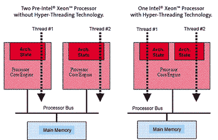
Intel’s Hyper-Threading Technology brings the concept of simultaneous multi-threading to the Intel Architecture. Hyper-Threading Technology makes a single physical processor appear as two logical processors; the physical execution resources are shared and the architecture state is duplicated for the two logical processors.

  • From a software or architecture perspective, this means operating systems and user programs can schedule processes or threads to logical processors as they would on multiple physical processors. 
  • From a micro architecture perspective, this means that instructions from both logical processors will persist and execute simultaneously on shared execution resources.

Hyper-Threading Technology makes a single physical processor appear as multiple logical processors [11, 12]. To do this, there is one copy of the architecture state for each logical processor, and the logical processors share a single set of physical execution resources. From a software or architecture perspective, this means operating systems and user programs can schedule processes or threads to logical processors as they would on conventional physical processors in a multiprocessor system. From a micro architecture perspective, this means that instructions from logical processors will persist and execute simultaneously on shared execution resources.
The first implementation of Hyper-Threading Technology is being made available on the Intel. Xeon processor family for dual and multiprocessor servers, with two logical processors per physical processor. By more efficiently using existing processor resources, the Intel Xeon processor family can significantly improve performance at virtually the same system cost. This implementation of Hyper-Threading Technology added less than 5% to the relative chip size and maximum power requirements, but can provide performance benefits much greater than that.
Each logical processor maintains a complete set of the architecture state. The architecture state consists of registers including the general-purpose registers, the control registers, the advanced programmable interrupt controller (APIC) registers, and some machine state registers. From a software perspective, once the architecture state is duplicated, the processor appears to be two processors.
The number of transistors to store the architecture state is an extremely small fraction of the total. Logical processors share nearly all other resources on the physical processor, such as caches, execution units, branch predictors, control logic, and buses. Each logical processor has its own interrupt controller or APIC. Interrupts sent to a specific logical only that logical processor handles processors.

BENEFITS OF HYPER THREADING TECHNOLOGY

High processor utilization rates: One processor with two architectural states enable the processor to more efficiently utilize execution resources. Because the two threads share one set of execution resources, the second thread can use resources that would be otherwise idle if only one thread was executing. The result is an increased utilization of the execution resources within each physical processor package.
 Higher performance for properly optimized software: Greater throughput is achieved when software is multi threaded in a way that allows different threads to tap different processor resources in parallel. For example, Integer operations are scheduled on one logical processor while floating point computations occur on the other.
Full backward compatibility: Virtually all multiprocessor-aware operating systems and multi threaded applications benefit from Hyper- Threading technology. Software that lacks multiprocessor capability is unaffected by Hyper-Threading technology.

Haptic Technology

Abstract

The basic idea of haptic devices is to provide users with a force feedback information on the motion and/or force that they generate. Haptic devices are useful for tasks where visual information is not sufficient and may induce unacceptable manipulation errors, for example surgery or teleoperation in radioactive/chemical environments.
The aim of haptic devices is to provide the user with a feeling of the situation. In this article we will try to review a particular type of haptic devices, namely those based on parallel mechanisms.
A haptic technology is a force or tactile feedback technology, which allows a user to touch, feel, manipulate, create, and/or alter simulated three-dimensional objects in a virtual environment. Such an interface could be used to train physical skills such as those jobs requiring specialized hand-held tools, for instance, surgeons, astronauts, and mechanics.Or to enable modeling of three dimensional objects without a physical medium such as automobile body designers working with clay models, to mock-up developmental prototypes directly from CAD databases rather than in a machine shop using virtual reality modeling language in conjunction with haptic technology.In addition, haptic help doctors to locate any change in temperature, or tumor in certain part of body without physically being there.
The term haptic is derived from the greek word 'haphe' which means pertaining to touch. The scientific term "haptics" refers to sensing and manipulation through the sense of touch. Although the word haptics may be new to many users, chances are that they are already using haptic interfaces.

Applications Of Haptic Technology

Haptic technology finds wide range of applications as mentioned below:
 Surgical simulation and medical training.

 Physical rehabilitation.

 Training and education.

• Museum display

 Painting, sculpting and CAD.

• Scientific visualization.

• Military application.

Haptic interface                                                                                

During the spring of 1993, MIT's work on haptic has introduced a new haptic interface that came to be called PHANTOM. This quickly commercialized due to strong interest from many colleagues and technically progressive corporations.Right now there are more than hundreds of PHANTOM haptic interfaces worldwide, this could represent an emerging market for haptic interface device.The PHANTOM interface is an electromechanical device small enough to sit on the surface of a desk and connects to a computer's input/output port.

Diamond chip

Abstract

Electronics without silicon is unbelievable, but it will come true with the evolution of Diamond or Carbon chip. Now a day we are using silicon for the manufacturing of Electronic Chip's.It has many disadvantages when it is used in power electronic applications, such as bulk in size, slow operating speed etc. Carbon, Silicon and Germanium are belonging to the same group in the periodic table.
They have four valance electrons in their outer shell. Pure Silicon and Germanium are semiconductors in normal temperature. So in the earlier days they are used widely for the manufacturing of electronic components. But later it is found that Germanium has many disadvantages compared to silicon, such as large reverse current, less stability towards temperature etc so in the industry focused in developing electronic components using silicon wafers
Now research people found that Carbon is more advantages than Silicon. By using carbon as the manufacturing material, we can achieve smaller, faster and stronger chips. They are succeeded in making smaller prototypes of Carbon chip. They invented a major component using carbon that is "CARBON NANOTUBE", which is widely used in most modern microprocessors and it will be a major component in the Diamond chip.

WHAT IS IT?

In single definition, Diamond Chip or carbon Chip is an electronic chip manufactured on a Diamond structural Carbon wafer. OR it can be also defined as the electronic component manufactured using carbon as the wafer. The major component using carbon is (cnt) Carbon Nanotube. Carbon Nanotube is a nano dimensional made by using carbon. It has many unique properties.


HOW IS IT POSSIBLE?

Pure Diamond structural carbon is non-conducting in nature. In order to make it conducting we have to perform doping process. We are using Boron as the p-type doping Agent and the Nitrogen as the n-type doping agent. The doping process is similar to that in the case of Silicon chip manufacturing. But this process will take more time compared with that of silicon because it is very difficult to diffuse through strongly bonded diamond structure. CNT (Carbon Nanotube) is already a semi conductor.

ADVANTAGES OF DIAMOND CHIP

1 SMALLER COMPONENTS ARE POSSIBLE

As the size of the carbon atom is small compared with that of silicon atom, it is possible to etch very smaller lines through diamond structural carbon. We can realize a transistor whose size is one in hundredth of silicon transistor.

2 IT WORKS AT HIGHER TEMPERATURE

Diamond is very strongly bonded material. It can withstand higher temperatures compared with that of silicon. At very high temperature, crystal structure of the silicon will collapse. But diamond chip can function well in these elevated temperatures. Diamond is very good conductor of heat. So if there is any heat dissipation inside the chip, heat will very quickly transferred to the heat sink or other cooling mechanics.

3 FASTER THAN SILICON CHIP

Carbon chip works faster than silicon chip. Mobility of the electrons inside the doped diamond structural carbon is higher than that of in he silicon structure. As the size of the silicon is higher than that of carbon, the chance of collision of electrons with larger silicon atoms increases. But the carbon atom size is small, so the chance of collision decreases. So the mobility of the charge carriers is higher in doped diamond structural carbon compared with that of silicon.

4 LARGER POWER HANDLING CAPACITY

For power electronics application silicon is used, but it has many disadvantages such as bulk in size, slow operating speed, less efficiency, lower band gap etc at very high voltages silicon structure will collapse. Diamond has a strongly bonded crystal structure. So carbon chip can work under high power environment. It is assumed that a carbon transistor will deliver one watt of power at rate of 100 GHZ. Now days in all power electronic circuits, we are using certain circuits like relays, or MOSFET inter connection circuits (inverter circuits) for the purpose of interconnecting a low power control circuit with a high power circuit .If we are using carbon chip this inter phase is not needed. We can connect high power circuit direct to the diamond chip

NEW TECH: (CONSTRUCTIVE DESTRUCTION) BY IBM:

Constructive destruction is new technique invented by IBM. It not a manufacturing method of carbon nanotube; but it is manipulated method. By the three methods mentioned above, we are getting both singled walled carbon nanotube and multi walled carbon nanotubes. All electronic applications require semi conducting carbon nanotubes. This method to separate semi conducting carbon nanotubes from metallic carbon nanotubes. It follows below step –
1. Deposit stick together carbon nanotubes on silicon dioxide water.
2. Use photographic methods to make electrodes on both ends of the carbon nanotube.
3. Make a gate electrode on the silicon dioxide water.
4. Using silicon dioxide water it self as the electrode, the scientist’s switched off. The semi conducting nanotubes by applying appropriate voltage to the silicon dioxide water. Which blocks any current flow through the semi conducting nanotube.
5. The metallic carbon nanotubes are unprotected, and appropriate carbon voltage is applied to destroy the metallic carbon nanotubes.
6. Result:- a dense array of un- harmed semi conducting carbon nanotubes are formed, which can be used for transistor manufacturing.

Atomic Force Microscope (AFM)

"Atomic force microscopy (AFM) is a method of measuring surface topography on a scale from angstroms to 100 microns. The technique involves imaging a sample through the use of probe or tip, with a radius of 20nm. The tip is held several nanometers above the surface using a feedback mechanism that measures surface-tip interaction on the scale of nano Newton’s. Variation in tip height are recorded while the tip is scanned repeatedly"
Across the sample, producing a topographic image of the surface. In addition to basic AFM, the instrument in the Microscopy Suite is capable of producing images in a number of other modes, including tapping, magnetic force, and pulsed force. In tapping mode, the tip is oscillated above the sample surface, and data may be collected from interactions with surface topography, stiffness, and adhesion.
This result in an expanded number of image contrast methods compared to basic AFM. Magnetic force mode imaging utilizing a magnetic tip to enable the visualization of magnetic domains on the sample. In electrical force mode imaging a charged tip is used to locate and record variations in surface charge. In pulsed force mode (Witec), the sample is oscillated beneath the tip, and a serious of pseudo force – distance curves are generated. This permits the separation of sample topography, stiffness, and adhesion values, producing three independent images. Or three individual sets of data , Simultaneously

3D Searching

Abstract

From computer-aided design (CAD) drawings of complex engineering parts to digital representations of proteins and complex molecules, an increasing amount of 3D information is making its way onto the Web and into corporate databases.Because of this, users need ways to store, index, and search this information. Typical Web-searching approaches, such as Google's, can't do this. Even for 2D images, they generally search only the textual parts of a file, noted Greg Notess, editor of the online Search Engine Showdown newsletter.
However, researchers at universities such as Purdue and Princeton have begun developing search engines that can mine catalogs of 3D objects, such as airplane parts, by looking for physical, not textual, attributes. Users formulate a query by using a drawing application to sketch what they are looking for or by selecting a similar object from a catalog of images. The search engine then finds the items they want. The company must make it again, wasting valuable time and money.

3D SEARCHING Introduction

Advances in computing power combined with interactive modeling software, which lets users create images as queries for searches, have made 3Dsearch technology possible.
Methodology used involves the following steps
  • " Query formulation
  • " Search process
  • " Search result

QUERY FORMULATION

True 3D search systems offer two principal ways to formulate a query: Users can select objects from a catalog of images based on product groupings, such as gears or sofas; or they can utilize a drawing program to create a picture of the object they are looking for. or example, Princeton's 3D search engine uses an application to let users draw a 2D or b of the object they want to find.
The  picture shows the query interface of a 3D search system.

SEARCH PROCESS

The 3D-search system uses algorithms to convert the selected or drawn image-based query into a mathematical model that describes the features of the object being sought. This converts drawings and objects into a form that computers can work with. The search system then compares the mathematical description of the drawn or selected object to those of 3D objects stored in a database, looking for similarities in the described features.The key to the way computer programs look for 3D objects is the voxel (volume pixel). 
A voxel is a set of graphical data-such as position, color, and density-that defines the smallest cubeshaped building block of a 3D image. Computers can display 3D images only in two dimensions. To do this, 3D rendering software takes an object and slices it into 2D cross sections. The cross sections consist of pixels (picture elements), which are single points in a 2D image.
To render the 3D image on a 2D screen, the computer determines how to display the 2D cross sections stacked on top of each other, using the applicable interpixel and interslice distances to position them properly. The computer interpolates data to fill in interslice gaps and create a solid image.

Wednesday, 30 December 2015

Biological Computers

Abstract

Biological computers have emerged as an interdisciplinary field that draws together molecular biology, chemistry, computer science and mathematics. The highly predictable hybridization chemistry of DNA, the ability to completely control the length and content of oligonucleotides, and the wealth of enzymes available for modification of the DNA, make the use of nucleic acids an attractive candidate for all of these nanoscale applications.
A 'DNA computer' has been used for the first time to find the only correct answer from over a million possible solutions to a computational problem. Leonard Adleman of the University of Southern California in the US and colleagues used different strands of DNA to represent the 20 variables in their problem, which could be the most complex task ever solved without a conventional computer. The researchers believe that the complexity of the structure of biological molecules could allow DNA computers to outperform their electronic counterparts in future.

Scientists have previously used DNA computers to crack computational problems with up to nine variables, which involves selecting the correct answer from 512 possible solutions. But now Adleman's team has shown that a similar technique can solve a problem with 20 variables, which has 220 - or 1 048 576 - possible solutions.
Adleman and colleagues chose an 'exponential time' problem, in which each extra variable doubles the amount of computation needed. This is known as an NP-complete problem, and is notoriously difficult to solve for a large number of variables. Other NP-complete problems include the 'travelling salesman' problem - in which a salesman has to find the shortest route between a number of cities - and the calculation of interactions between many atoms or molecules.
Adleman and co-workers expressed their problem as a string of 24 'clauses', each of which specified a certain combination of 'true' and 'false' for three of the 20 variables. The team then assigned two short strands of specially encoded DNA to all 20 variables, representing 'true' and 'false' for each one.
In the experiment, each of the 24 clauses is represented by a gel-filled glass cell. The strands of DNA corresponding to the variables - and their 'true' or 'false' state - in each clause were then placed in the cells.
Each of the possible 1,048,576 solutions were then represented by much longer strands of specially encoded DNA, which Adleman's team added to the first cell. If a long strand had a 'subsequence' that complemented all three short strands, it bound to them. But otherwise it passed through the cell.
To move on to the second clause of the formula, a fresh set of long strands was sent into the second cell, which trapped any long strand with a 'subsequence' complementary to all three of its short strands. This process was repeated until a complete set of long strands had been added to all 24 cells, corresponding to the 24 clauses. The long strands captured in the cells were collected at the end of the experiment, and these represented the solution to the problem.

DOCTOR IN A CELL

In previous Biological computers produced input, output and "software" are all composed of DNA, the material of genes, while DNA-manipulating enzymes are used as "hardware." The newest version's input apparatus is designed to assess concentrations of specific RNA molecules, which may be overproduced or under produced, depending on the type of cancer. Using pre-programmed medical knowledge, the computer then makes its diagnosis based on the detected RNA levels.
In response to a cancer diagnosis, the output unit of the computer can initiate the controlled release of a single-stranded DNA molecule that is known to interfere with the cancer cell's activities, causing it to self-destruct.

Rain Technology

Abstract

Rain finity's technology originated in a research project at the California Institute of Technology (Caltech), in collaboration with NASA's Jet Propulsion Laboratory and the Defense Advanced Research Projects Agency (DARPA).The name of the original research project was RAIN, which stands for Reliable Array of Independent Nodes. The goal of the RAIN project was to identify key software building blocks for creating reliable distributed applications using off-the-shelf hardware.
The focus of the research was on high-performance, fault-tolerant and portable clustering technology for space-borne computing. Two important assumptions were made, and these two assumptions reflect the differentiations between RAIN and a number of existing solutions both in the industry and in academia:
1. The most general share-nothing model is assumed. There is no shared storage accessible from all computing nodes. The only way for the computing nodes to share state is to communicate via a network. This differentiates RAIN technology from existing back-end server clustering solutions such as SUNcluster, HP MC Serviceguard or Microsoft Cluster Server.
2. The distributed application is not an isolated system. The distributed protocols interact closely with existing networking protocols so that a RAIN cluster is able to interact with the environment. Specifically, technological modules were created to handle high-volume network-based transactions. This differentiates it from traditional distributed computing projects such as Beowulf.
In short, the RAIN project intended to marry distributed computing with networking protocols. It became obvious that RAIN technology was well-suited for Internet applications. During the RAIN project, key components were built to fulfill this vision. A patent was filed and granted for the RAIN technology. Rainfinity was spun off from Caltech in 1998, and the company has exclusive intellectual property rights to the RAIN technology. After the formation of the company, the RAIN technology has been further augmented, and additional patents have been filed.
The guiding concepts that shaped the architecture are as follows:

1. Network Applications

The architecture goals for clustering data network applications are different from clustering data storage applications. Similar goals apply in the telecom environment that provides the Internet backbone infrastructure, due to the nature of applications and services being clustered.

2. Shared-Nothing

The shared-storage cluster is the most widely used for database and application servers that store persistent data on disks. This type of cluster typically focuses on the availability of the database or application service, rather than performance. Recovery from failover is generally slow, because restoring application access to disk-based data takes minutes or longer, not seconds. Telecom servers deployed at the edge of the network are often diskless, keeping data in memory for performance reasons, and tolerate low failover time. Therefore, a new type of share-nothing cluster with rapid failure detection and recovery is required. The only way for the shared-nothing cluster to share is to communicate via the network.

3. Scalability

While the high-availability cluster focuses on recovery from unplanned and planned downtimes, this new type of cluster must also be able to maximize I/O performance by load balancing across multiple computing nodes. Linear scalability with network throughput is important. In order to maximize the total throughput, load load-balancing decisions must be made dynamically by measuring the current capacity of each computing node in real-time. Static hashing does not guarantee
an even distribution of traffic.

4. Peer-to-Peer

A dispatcher-based, master-slave cluster architecture suffers from scalability by introducing a potential bottleneck. A peer-to-peer cluster architecture is more suitable for latency-sensitive data network applications processing shortlived sessions. A hybrid architecture should be considered to offset the need for more control over resource management. For example, a cluster can assign multiple authoritative computing nodes that process traffic in the round-robin order for each network interface that is clustered to reduce the overhead of traffic forwarding.

Bluetooth Broadcasting

Abstract

Bluetooth wireless technology (IEEE 802.15.1) is a short-range communications technology originally intended to replace the cables connecting portable and/or fixed devices while maintaining high levels of security.The key features of Bluetooth technology are threefold:
  • robustness
  • low power
  • low cost.
 Bluetooth has been designed in a uniform way. This way it enables a wide range of devices to connect and communicate with each other by using the Bluetooth wireless communication protocol. The Bluetooth technology has achieved global acceptance in such a way that any Bluetooth-enabled electronic device, almost everywhere in the world, is able to connect to other Bluetooth-enabled devices in its proximity.
Bluetooth-enabled electronic devices connect and communicate wirelessly through short-range, ad hoc networks known as piconets. Each device can simultaneously communicate with up to seven other devices within a single piconet. Each device can also belong to several piconets simultaneously. Piconets are established dynamically and automatically as Bluetooth-enabled devices enter and leave radio proximity. One of the main strengths of the Bluetooth wireless technology is the ability to handle data and voice transmissions simultaneously. This enables users to use a hands-free headset for voice calls, printing, fax capabilities, synchronizing PDA’s, laptops, and mobile phone applications to name a few.
An important aspect of this thesis is about the scalability of Bluetooth broadcasting. Since scalability can sometimes be a rather vague concept, we give a short explanation of the term. An important aspect of software products is how they are able to cope with growth. For example, how does the system handle an increase in users or data traffic? This property of a software system is usually referred to as scalability. A more detailed specification of the concept is given by AndrĂ© Bondi, who defines it as follows: ‘Scalability is a desirable attribute of a network, system, or process.
The concept connotes the ability of a system to accommodate an increasing number of elements or objects, to process growing volumes of work gracefully, and/or to be susceptible to enlargement.’ Whenever a system meets these requirements we can say that the system scales. In this thesis scalability comes down to the question if the system is capable of dealing with large groups of users equipped with Bluetooth enabled devices capable of receiving simple text messages.

Passive Broadcasting

The first type of business deals with broadcasting from a central location, which we will call passive broadcasting. Most of these companies sell both the hardware and software to enable this. For example, BlueCasting by Filter WorldWide, one of the major players in the market which made the news in August 2005 when they distributed merchandise for the British pop band Coldplay, offers a product family divided into four types of systems. They offer solutions for small retail shops, one-off events such as music festivals, and even larger areas such as airports and train stations.
The latest descendant in the family is a system that provides an interactive touchscreen allowing users to interact directly with the system. BlueCasting is an example of a product that comes with both hardware (one or more BlueCast Servers) and software (BlueCast Campaign Management System) which is used to provide remote setup, maintenance and reporting.Besides this type of companies, i.e. the ones that are selling the total package, other companies have dedicated themselves to providing just the hardware. An example is BlueGiga. According to their website their BlueGiga Access Servers are used by more than 350 Bluetooth Marketing companies in more than 65 countries. They sell two lines of products: Bluetooth Modules and Bluetooth Access Servers. The modules are described as ‘completely integrated, certified, high-performance Radio Frequency products including all needed Bluetooth profiles’.
Access Servers are sold in the form of Access Points (up to 7 connections) and Access Servers (up to 21 connections). Besides this they also sell the BlueGiga Solution Manager (BSM). This is a web-based remote management and monitoring platform for BlueGiga Access Servers that can be used to simultaneously upgrade, monitor and configure a large number of BlueGiga Access Servers, instead of configuring each device one-by-one.

Bluetooth Core System Architecture :

The transceiver operates in the globally unlicensed ISM band at 2.4 GHz. The bit rate
is 1 Megabit per second and can be boosted to 2 or 3 Mb/s with Enhanced Data Rate[EDR]. The 79 channels in the band are ordered from channel number 0-78 and are spaced 1 MHz beginning at 2402 GHz. Bluetooth-enabled devices that are communicating share a radio channel and are synchronized to a common clock and frequency hopping pattern. Frequency hopping is used to make the protocol more-robust to interference from other devices operating in the same band.
The physical channel is sub-divided into time units known as slots. Data is transmitted between Bluetooth-enabled devices in packets. These packets are situated in the slots. Packets can fill one or more consecutive slots, allowing larger data chunks to be transmitted if the circumstances admit this. Bluetooth is primarily designed for low power consumption and affordability and has a relatively short range (1, 10 or 100 meters). It makes use of low-cost transceiver microchips that are embedded in each device.
The Bluetooth Base band is the part of the Bluetooth system that specifies or implements the medium access and physical layer procedures between Bluetooth devices. Several devices can be joined together in what is called a piconet. One device owns the clock and the frequency hopping pattern and is called the master. Two or more piconets can be joined in what is called a scatternet. To form a scatternet, some units, called gateways, belong to different piconets. Such a unit can be a slave unit in more than one piconet but can act as a master in only one.

Besides this, it can transmit and receive data in only one piconet at a time. To visualize this, imagine the following. You are on the phone with a friend, using your Bluetooth headset, while at the same time you are uploading pictures from your computer to your phone. Your phone now acts as a gateway, being the master in the piconet with your headset and slave in the one with your computer.